
Cable Ladder, Bends, Cable Duct, Cable Tray

Overview
Tray System
Advantages
Specification
Straight Section
Pre-Assesmbled Fittings
Spice Plate
Instrumentation/
Light Load CablesApplication
Mode:LTFTY
Accessories
Overview
Fiberglass reinforced plastic (FRP) anti-corrosion cable bridge or tray is made of glass fiber, epoxy resin and other special materials, it has reasonable mechanical structure, light weight,high strength, strong corrosion resistance, flame retardance, aging resistance and good insulation performance, it can be used in a large range of temperature and the environments of high humidity, heavy acid and or heavy alkali.


The service life is 5-6 times of the steel bridge, the installation distance of one ton of FRP cable bridge or tray is 1.5 times of the steel bridge with same specification and same weight.
FRP cable bridge can be overhead laying; erected under the beam or floor slab,can be fixed laterally by indoor and outdoor walls, posts, tunnels, cable trench walls., can also be installed in the open air.
A complete FRP cable tray is composed of straight run, horizontal bend, horizontal tee, horizontal cross, straight reducer, left reducer, right reducer, vertical outside bend, vertical inside bend connected with splice plates, clamps, brackets, etc.
Tray System
COMPANY PROFILE:
At FIBRETRAY is known for the quality performance of its fiberglass products be it Cable Trays, Street Light Poles, Ladders, Enclosures, Cable Cleats, Cable Supports, Gratings, Handrails.
It is a company promoted by a group manufacturing industrial electrical and instrumentation products for last three decades, specially designed for the use in critical environment.
Fiberglass products were specifically developed due to demand from the valued wide client base.
FIBRETRAY Cable Tray provides reliable cable support in corrosive application. Both polyester and vinyl ester resin systems are available & all components incorporating U. V. stabiliser and a surfacing veil to resist corrosive atmosphere. The cable trays manufactured by us are from pultruded sections / profiles of fiberglass, this pultruded sections help in reducing cost, achieving quality, perfection for optimum performance of the tray.
At FIBRETRAY we have in house facility of producing pulruded sections as well as other accessories with multiple production lines. We at FIBRETRAY produce Cable Trays, as well as molded & metered fittings as well as other accessories like coupler plates, struts, and many more. From power plants to fertiliser industries, paper mills to refineries to laboratories, sound electrical design requires an adaptable cable support system that is reliable. Above all durability and resistance to corrosion lead to lower costs during the life of installation.

Design Specification:
Our Cable Tray System meets the requirement ofNEMA (National Electric Manufacturers Association) FG I-1993 (Current Issue) for FIBERGLASS CABLE TRAY SYSTEM. Specifications of Engineers India Ltd. UL (Underwriters Laboratories, Inc) Standards for NON- Metallic Cable Tray. NEMA VE 2-2001 Cable Tray Installation Guideline.as well as clientsspecification / requirements. We can supply Zero Halogen, Halogen Free, Antistatic and Static Dissipative Products on request.
Working Load Capacity
The working load capacity represents the ability of a fibreglass cable tray to support the static weight of cables. It is equivalent to destructive load capacity, with minimum safety factor of 1.5
As Per General Specifications

Concentrated Static Load is 70 Kg. at the centre of the span.
As Per Nema Loading Standards:

support span: 8,10,12 are in feet

Advantages
- Low cost, significant cost savings compared to standard traditional tray products.
- Light in weight, wide range of sizes.
- Fast heat dispersion. Strong enough to withstand short circuits. Provides strength, rigidity without additional hardware.
- Adapts to difficult architectural designs to accommodate changes in direction and elevation of cable runs.
- Flexible, easy and fast installation.
- Design allows cable exit or entry at any point. Cables can be secured to clamps or ties.
- Various hardware accessories available to fix, support and install.
- Safe smooth edge design to protect cable.
- Easy for line check and cleaning, easy maintained.
- All sharp ends are cut off to protect cables. Weight loading capacity is 27% stronger than traditional cable trays and cable ladders.


Specification
STANDARDS APPLICABLE
1.1
IS 6746-1994 Specs for Unsaturated Polyester Resin systems for Low Pressure Fibre Reinforced Plastics
1.2
NEMA FG 11984-1993 (current issue) Specifications for fibreglass Tray System -Loading Characteristics.
1.3
IS 6746-Appendix-K/UL 94 Flame Retardant (law flammability/Vo)
TECHNICAL DETAILS
2.1
Side Member FRP Pultruded ‘C’ Section.
2.2
Rung Sq. Hollowtube 25mm X25mm.
2.3
Construction/assembly of tray. The rungs to side member are connected, will have both mechanical & adhesive lock. The tray shall be assembled by use of a locking pin made of fibreglass reinforced thermoplasitc. The locking pin is inserted under pressure by machine with a high strength adhesive. All the bonded parts are surface prepared for maximum adhesion. All straight sections are pre drilled for Coupler plates. All cut ends shall be resin coated.
2.4
Length of Cable Tray 3000mm, 6000mm.
2.5
Width of cable Tray 150mm/ 300mm/450mm/ 600mm/750mm/900mm.
2.6
Rung Spacing 250mm/300mm.
2.7
Radius of Fittings 300mm, 600mm, 900mm.
2.8
Material of Side Member & Rung Corrosion Resistant Polyester-Isopthelic / vinyl ester, Flame Retardant U.V. Stabilised Resin System and Various types of Glass Fibre. Minimum Glass Content 55 to 60% in all pultruded sections and 30 to 40% for flat sheets and other moulded parts.
2.9
Ultra Violate Radiation protection: All the composite materials shall have UV Light inhabiting chemical additives to resist degradation from UV.
2.10
Flame Retardancy All the composite material shall be are retardants & will have same spread of 25 or less (Class Rating) when tested in accordance with ASTM D 635. Pultruded parts are provided with surface veil to achieve maximum chemical resistance.
ACCESSORIES/FITTINGS
All fittings are pre fabricated & will be same specification as of straight trays.
CONNECTION/COUPLER PLATE & SPLICE PLATES
FRP / Stainless steel Splice plates of various types ie.straight as well as adjustable for angles. This plates should be installed between 0.2 & 0.3 of the length of span of the support. Fastner of SS 304 / SS 316 shall be provided of 6mm/8mm diameter.
TYPICAL PROPERTIES OF PULTRUDED SECTIONS
5.1
ASTM-D-2863-Oxygen Index-30%.
5.2
ASTM-D-635-Flame Spread (Extent of burning) – 25 mm.
5.3
ASTM-D-638-Tensile Strength at break – 30,000 PSI.
5.4
ASTM-D-790- Flexural Strength at break – 30,000 PSI.
5.5
ASTM-D-256-Izod Impact Strength – 25 Ft.-LBS.
5.6
ASTM-D-149 – Electric Strength short terms Oil – 35 Kv/inch. 5.3 Surface Resistivity – >10120.
CORROSION RESISTANCE OF RESIN SYSTEM
Two standard composites resin systems are available. For most of the application polyester fire retardant (FR-P) is widely used. A vinyl ester composites fire retardant resin system (FR-VE) is used where strong acide (like hydrochloric acid), strong alkalis (like Caustic Soda), organic solvents and halogenated organic conditions exist. fibreglass cable trayincorporates a synthetic veil on the surface of all structural shapes which causes a resin rich layer which enhances corrosion protection. An abbreviated guide can be provided on request to assist in the selection of the proper resin system for individual application.
Straight Section
- FIBRETRAY cable tray is available in polyester as well as vinyl ester resin system.
- Our cable tray has a ‘C’ section as side rail.
- Our cable tray has a square type rung & rung connection is made with mechanical & adhesive lock.


TYPES AVAILABLE FOR CABLE TRAY SYSTEM

CATALOG NUMBERING SYSTEM
FRP / Stainless steel Splice plates of various types ie.straight as well as adjustable for angles. This plates

Example to create a catalog. SLC4P-12-12-10=Polyester cable tray with 300mm width & 300mmrung spacing in the length of 10 Ft.
* 450MM RUNG SPACING
NOT RECOMMENDED FOR 30 & 36 WIDTH
Cover For Ladder Type Cable Tray
Cable trays covers are required only for those area where the cable needs to be protected from falling objects. The covers are available in Polyester as well as vinyl Ester resin system. The covers will be 3Mtr / 10ft. and the thickness of the covers are normally 3mm if not specified.
FLAT COVER
Covers can be fitted with the help of thermoplastic stand off. It is recommended to use this studs at 600mm center along both side rails. This stand off is a separate item & can be supplied with the SS 304 hardware. Flat covers are available for straight trays as well as for accessories.

COVER CATALOG NO

PEAKED COVER
Covers can be fitted with the help of thermoplastic stand off. It is recommended to use this studs at 600mm center along both side rails. This stand off is a separate item & can be supplied with the SS 304 hardware. Peaked covers are available for straight trays only.

COVER CATALOG NO

On all illustrations for Ladder Type Trays (W) = Width of theinside distance form Tray wall to tray wall
Pre-Assesmbled Fittings


Spice Plate
Splice Plate For Ladder Type Cable Tray
FIBRETRAY offers fiberglass as well as stainless steel connector plates designed to connect between straight sections & fittings. Sizes of bolts used for connectors plates are 8mm X 25mm, hex bolt with nut, 2plain washer & 1 spring washer. This bolts are available in SS 304 & SS 316.
Catalog Numbering System

45° VERTICAL SPLICE PLATE: FVP-_-45

DIMENSION OF SPLICE PLATES IN MM.

Splice Plate For Ladder Type Cable Tray

Instrumentation/Light Load Cables
Pre Assembled Fittings For Instrumentation Cable Trays
The pre assembled fittings are available in all the type of tray. The fittings are assembled with the help of Stainless steel SS304 fasteners unless & otherwise specified.
90° INSIDE VERTICAL BEND

90° OUTSIDE VERTICAL BEND

90° HORIZONTAL BEND

HORIZONTAL CROSS


HORIZONTAL TEE


Splice Plates For Instrumentation Cable Trays
FIBRETRAY offers fiberglass as well as stainless steel connector plates designed to connect between straight sections & fittings.
Sizes of bolts used for connectors plates are 6mm x 25mm, hex bolt with nut, 2 plain washer & 1 spring washer. This bolts are available in SS 304 & SS 316.
DIMENSION OF SPLICE IN MM.


Catalog Numbering System


Cable Tray Accessories


FRP Cable Tray Support


Instrumentation/Light Load Cables
THE ELECTRIC CABLE TRAY SYSTEM ARE WIDELY USED FOR:


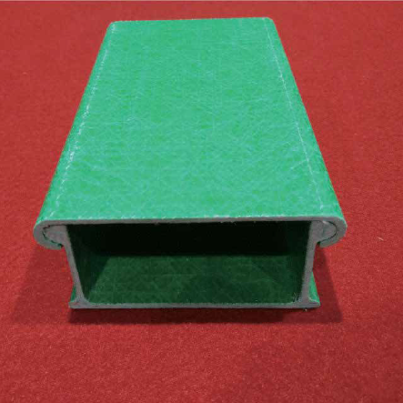
Mode:LTFTY
MODE:
LTFTY-C
THROUGH CABLE TRAY
Trough Cable Tray
It is a full-closed cable trays, which is applied to the laying of cables, telecommunications cables, thermocouple cables and other highly sensitive system of control cables.

Installation Instruction

MODE:
LTFTY-T
TRAY TYPE CABLE
Tray Type Cable Tray
Ilt is a structure consisting of bottom (ventilated or solid) with the longitudinal siderails. Widely used in petroleum, chemical industry,light industry, television,telecommunications,etc.

Installation Instruction

Trough Cable Tray And Tray Type Cable Tray

MODE:
LTFTY-L
LADDER CABLE TRAY
Ladder Cable Tray
Ladder Cable Tray systems consists of two longitudinal side members connected by individual transverse members, and is designed for use as a power cable or control cable support system.

Installation Instruction

Ladder Cable Tray

Accessories
Intallation Notice
- Each ends of cable trays should be connected by 6 holes when the height is 50-100 mm; when their height is 150-220 mm, holes should be 12.
- Support distance: it should not be more than the support distance and load capacity allowed by load curve.
- Width of cable trays: some remarkable room should be served when you choosing the cable trays width, in order to add cables in the near future.
- Laying separately: when electric cables and controlling cables are few, they could be laid in the same cable tray, as long as they are laid separately by clapboard.
- Fixing cables: when collecting cable trays are laid horizontally, connections among trays should be set on 1/4 of skip distance, horizontal cables should be fixed every 2 meters, and vertical cables should be fixed every 1.5 meters.
- Cable trays device should have another grounding equipment.

